工業設備技術領導者 (儲冰槽、冷卻水塔、發電機激磁系統)
Global Leader in Ice Thermal Storage
![]()
Cooling towers provide evaporative cooling for many types of systems. The specific application will largely determine which BAC Cooling Tower is best suited for a project.
Specific application assistance is available through your local BAC Representative.
Principle of Operation
Cooling towers reject heat from water-cooled systems to the atmosphere. Hot water from the system enters the cooling tower and is distributed over the fill (heat transfer surface). Air is induced or forced through the fill, causing a small portion of the water to evaporate. This evaporation removes heat from the remaining water, which is collected in the cold water basin and returned to the system to absorb more heat. Each cooling tower line, although operating under the same basic principle of operation, is arranged a little differently.
Configuration
There are two main configurations of factory assembled cooling towers: crossflow and counterflow. In crossflow cooling towers, the water flows vertically down the fill as air flows horizontally across. In counterflow cooling towers, the water flows vertically down the fill as air flows vertically up.
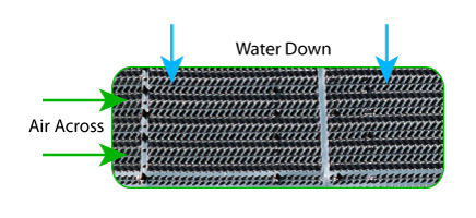
Crossflow Configuration
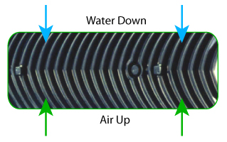
Counterflow Configuration
Water Distribution System
Gravity Distributuion Basin
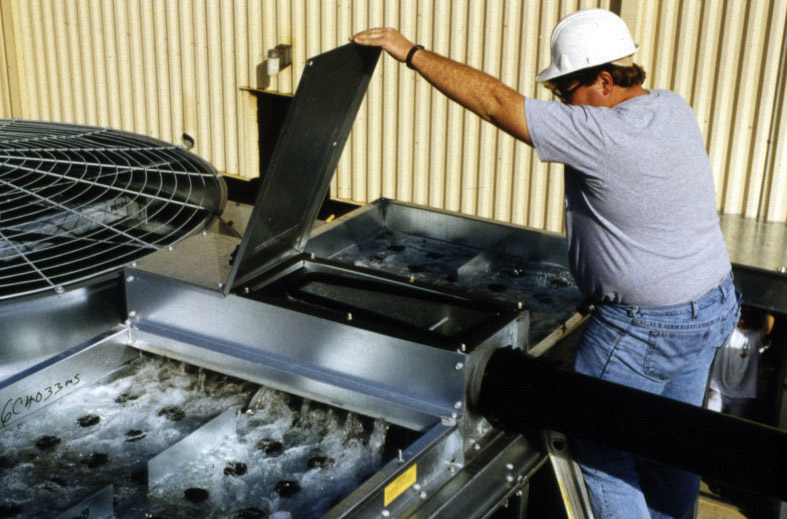
Cooling towers employ either gravity distribution or pressurized spray systems to distribute water over the fill. Gravity systems, employed on BAC’s crossflow cooling towers, feature hot water basins mounted on top of the tower above the fill. A series of spray nozzles in each hot water basin distribute the water evenly over the fill. Gravity distribution systems generally require minimal pump head, can be inspected while the unit is in operation and are easy to access for routine maintenance and service.
Spray distribution systems, employed on counterflow cooling towers, feature a series of PVC branches or pipes fitted with spray nozzles mounted inside the tower above the fill. These systems typically require 2 to 7 psi water pressure at the water inlet and require the unit to be out of service for inspection and maintenance.
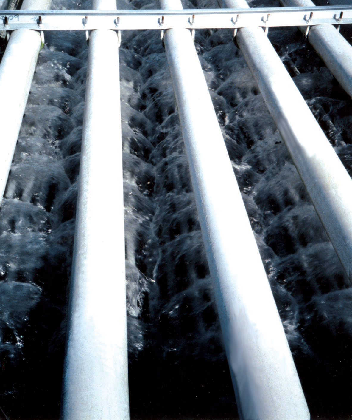
Spray Distribution
Fan System
The flow of air through most factory assembled cooling towers is provided by one or more mechanically driven fans. The fan(s) may be axial or centrifugal, each type having its own distinct advantages. Axial fan units require approximately half the fan motor horsepower of comparably sized centrifugal fan units, offering significant energy savings.

Centrifugal Fan
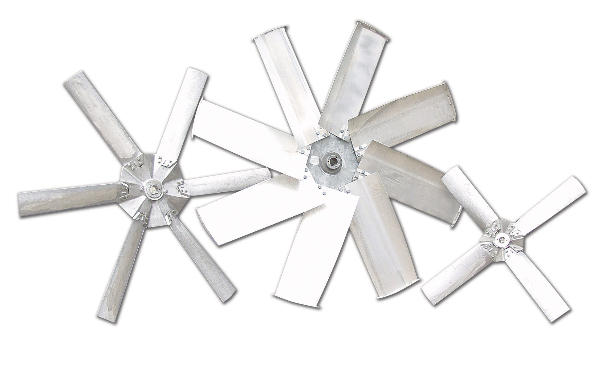
Axial Fan
Centrifugal fan units are capable of overcoming reasonable amounts of external static pressure (? 0.5” or 12.7mm of H2O), making them suitable for both indoor and outdoor installations. Centrifugal fans are also inherently quieter than axial fans, although the difference is minimal and can often be overcome through the application of optional low sound fans and/or sound attenuation on axial fan units.
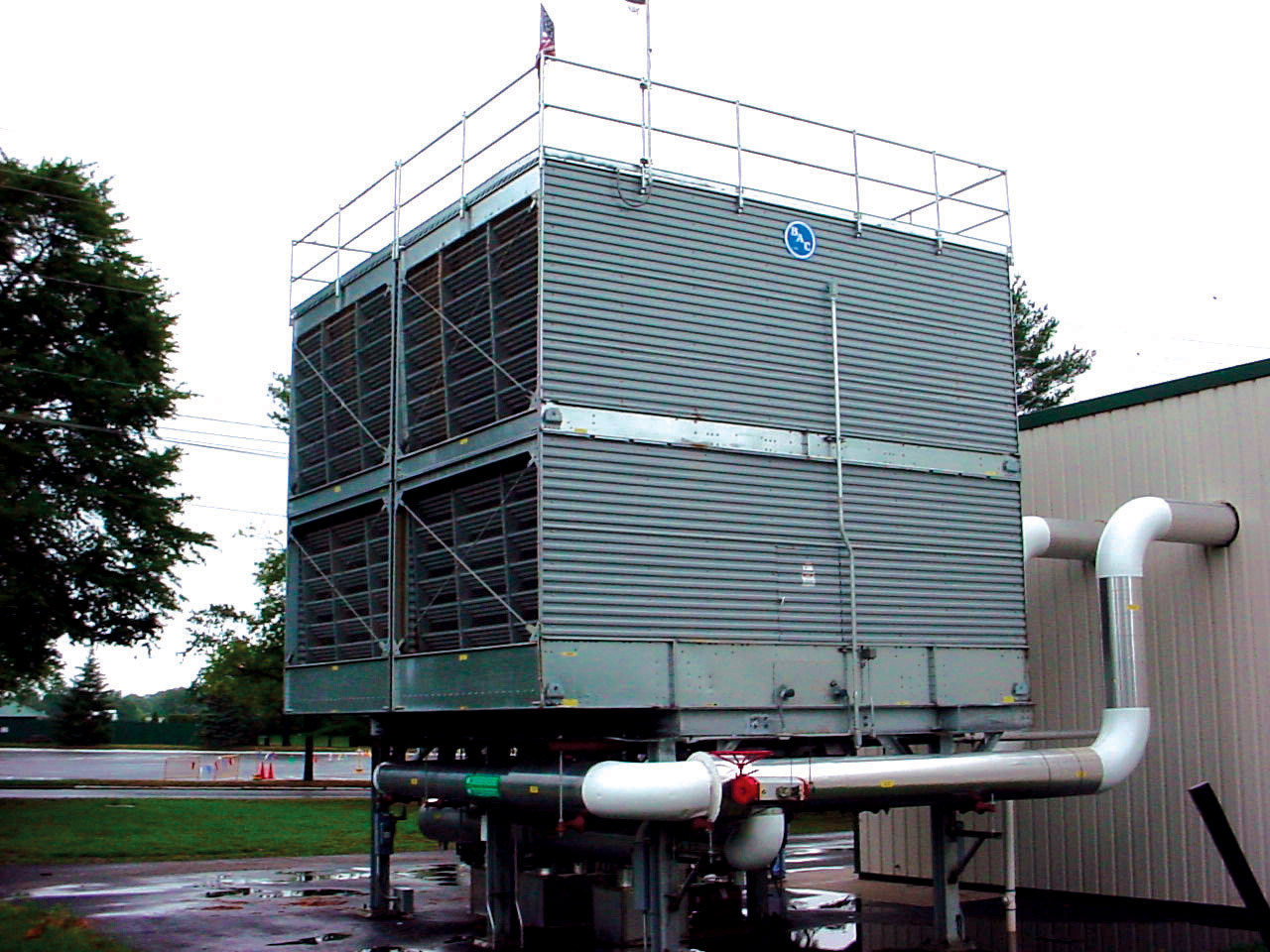
Induced Draft
The axial fans of induced draft equipment are mounted in the top deck of the unit, minimizing the impact of fan noise on nearby neighbors and providing maximum protection from fan icing with units operating in sub-freezing conditions. The use of corrosion resistant materials ensures long life and minimizes maintenance requirements for the air handling components.
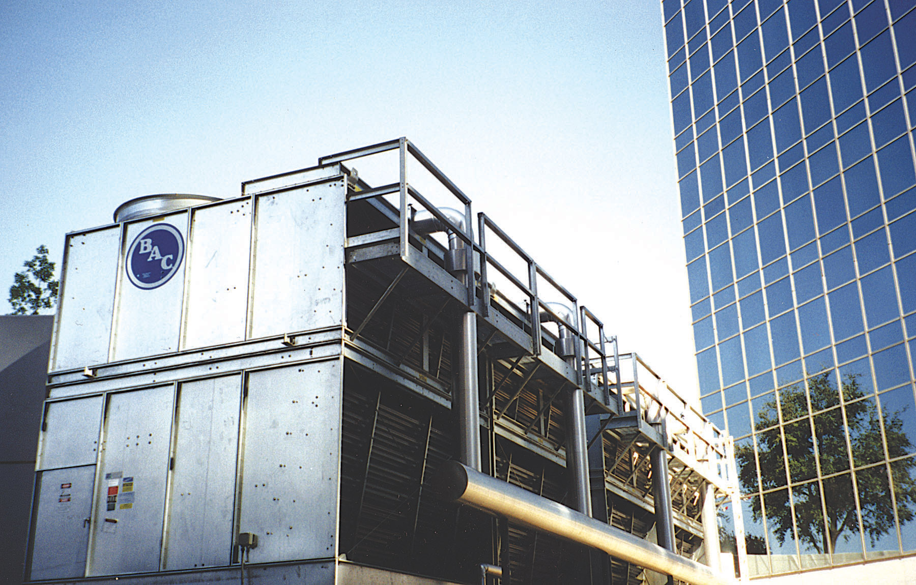
Forced Draft
The fans are located on the air inlet face at the base of forced draft towers, facilitating easy access for routine maintenance and service. Additionally, the location of these components in the dry entering air stream extends component life by isolating them from the saturated discharge air.
Capacity Range
Product capacities are called out in terms of nominal tons. A nominal cooling tower ton is defined as the capability to cool 3 GPM (0.19 lps) of water from a 95oF (35.0oC) entering water temperature to an 85oF (29.4oC) leaving water temperature at a 78oF (25.6oC) entering wet-bulb temperature. Nominal conditions are typical of conventional HVAC designs in most parts of the country, but will not apply to all projects. BAC offers selection software to evaluate the performance of a tower at many conditions.
All capacities shown in the comparison table are for a single cell. Multiple cell selections can be applied to achieve larger capacities.
Maximum Entering Water Temperature
As previously stated, typical HVAC conditions call for an entering water temperature of approximately 95oF (35.0oC). All BAC Cooling Towers are capable of withstanding temperatures of at least 120oF (48.9oC) with standard fill materials. For applications where the entering water temperature exceeds 120oF (48.9oC) view the comparison table to determine whether alternate fill materials are required for your project.
關注我們